
In this post, you will learn to how to switch a LED with the 2N3904 and 2N3906 BJT transistor. First, you will start to evaluate the current capabilities of the transistor itself, then calculate the circuity and finally to test it.
Transistor switching has been a revolution for computing and technology. This device grants control of other electric and electronic circuitry. And its fast.
Table of Contents
Requirements for Push Buttons
Components and Devices
In this tutorial, all the components are Through Hole.
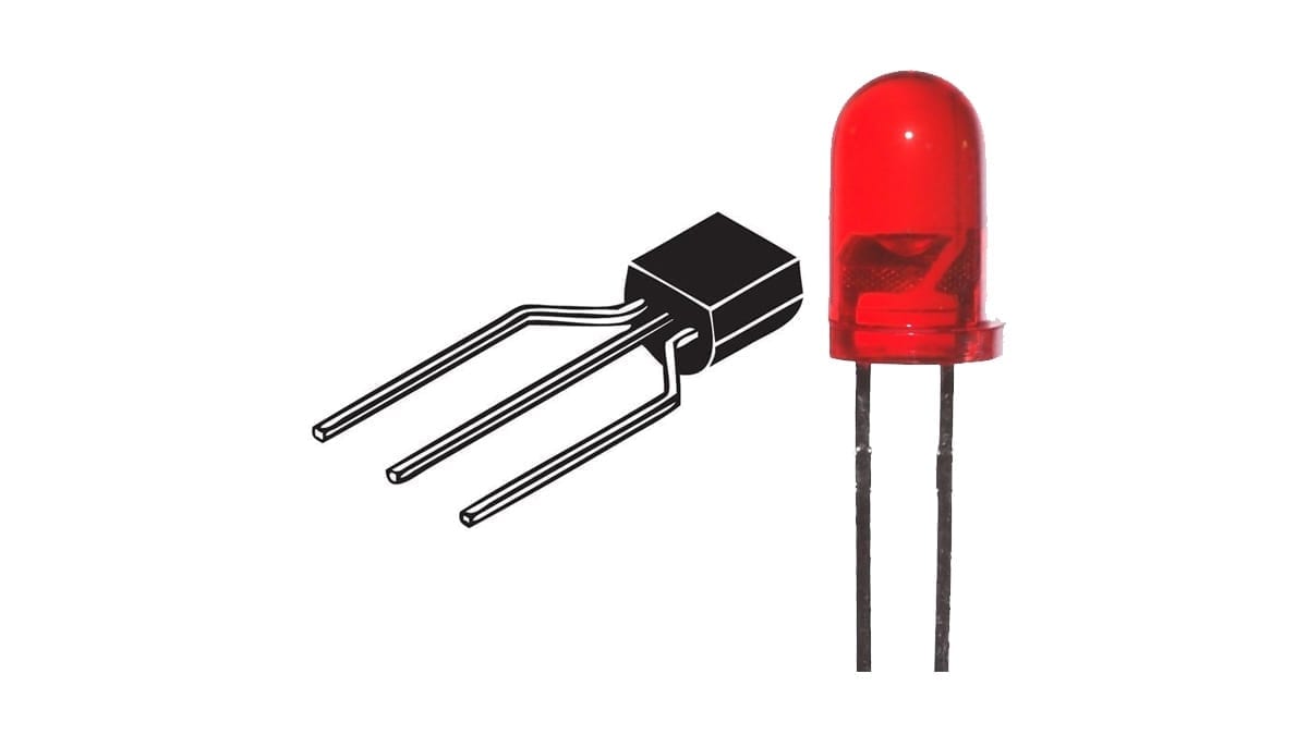
- 2N3904, BJT NPN transistor with TO-92 package: 1 unit.
- 2N3906, BJT PNP transistor with TO-92 package: 1 unit.
- LED, any size or color: 1 unit.
- Push button, type SPST: 1 unit.
- Resistors:
- 330Ω, 1/2 or 1/4W: 1 unit.
- 10KΩ, 1/2 or 1/4W: 1 unit.
- 100KΩ, 1/2 or 1/4W: 1 unit.
- 68KΩ, 1/2 or 1/4W: 1 unit.


Tools and Machinery
- Breadboard: 1 unit.
- AC/DC Power Adapter to 5V DC, with at least 500mA: 1 unit.
- Jumper or UTP Wires: various.
- Multimeter: 1 unit.


The Circuit for Switching
The Parameters needed
Before we figure out the appropriate components, let's find out the requirements for the circuit to work properly. In this case, the 2 most important parameters are the current and the voltage.
The circuit used is a 5mm LED in series with a 330Ω 1/4W resistor. This works perfectly fine with a 5v power source.
The circuit before the Transistor

This circuit is very simple. The resistor and the LED. The push button is only required for demonstration purposes.
Measuring Voltage, Current and Gain
First, use the voltmeter in DC voltage (in 20V scale) and measure the voltage of the power supply of the circuit. Afterwards, use the ampmeter in DC current (in scale of 200mA) to measure how much current is using the circuit.


These are the measured values of my circuit:
| Measurement | Value |
| DC Voltage (V) | 5.28 |
| DC Current (ma) | 9.84 |
Examining the Transistor
Switching Schematic

This circuit serves the purpose of a basic switching. The left ilustrates the switching schematic for the 2N3904 NPN, while the equivalent for the 2N3906 PNP is on the right.
The NPN is switched on when (enough) current is flowing into the base of the transistor, while the PNP is switched on when (enough) current is drawn from its base.
The collector is connected to the circuit that we actually want to switch, where more current flows. The emitter (for this switching model schematic) should be connected either to the ground (NPN) nor to the power source (PNP).
Referring to the Datasheet
How much current should flow through the base? It will depend of every transistor since each transistor model has different characteristics.
Let's look at the datasheet at 2 common general purpose BJT transistors: the NPN 2n3904 and the PNP 2n3906. Both will be used here.
Voltage
Since the maximum voltage is going to be 5V, the circuit doesn't reach any of the maximums of Collector−Emitter Voltage or Collector−Base Voltage.
Current
The Collector Current − Continuous is 200mA, which is more than enough current to switch the LED (9.84mA).
Gain
The ratio between the collector current ‘Ic‘ and the base current ‘Ib‘ is called HFE gain (sometimes called β). The more current that flows through Ib, the more current will flow through Ic, theoretically. The current Ic is proportionately dependent on the value of Ib; it's translated to the following formula:
Ic = Ib * HFE
How much gain does the transistor has? It depends. It's not a one constant number. It varies on conditions such as temperature, collector current, etc. A few results under certain conditions can be found on the datasheet.
But let's use the HFE measurement tool from the multimeter to find out an approximately value. Connect the transistor to the collector, emitter and base sockets of the HFE measurement. If it's the 2n3904, then insert in the NPN socket and select the ‘NPN' mode. If it's the 2n3906, then in the PNP socket and select the ‘PNP' mode. (The mode selector will vary from multimeter to multimeter).


After measuring it, we will use 150 as the value of HFE for the calculation.
Base Resistor
In this circuit, the same power supply will be used for the collector and the base circuits. But they could be different.
The gain HFE between the Ic and Ib are required to calculate the resistor in the base Rb. First let's find out Ib:
Ib=Ic/HFE=9.84mA/148=0,066mAHow big should be resistor Rb to allow just 0,066mA to flow? Bear in mind that you have to consider the 0,7V voltage drop across the diode (from base to emitter). Let's find out Rb:
Rb=(Vcc-Vd)/Ib=(5,28V-0,7)/0,066mA=69,39KΩThe closest commercial value for this transistor is 68KΩ, so this will be the resistor base Rb.
Final Numbers
After the calculations and referring to the schematic above, these are going to be the used values, shown in Ω (Ohms).
| Rc | 330 |
| Rb | 68K |
Testing the LED switching
First Impression Result


When the circuit is turned on (from the power supply) the LED do not shine. When the push button is pressed, the LED starts to shine. This means that the switch operation was successful because the transistor does the job.
Measuring Values
The LED and the 330Ω resistor has a voltage drop of 4.81V and the transistor from the collector to the emitter has 0.44V, which means that this switch “steals a little” voltaje from the LED and 330Ω resistor circuit. But it turns out that it's negligible. It works pretty good!
What about the currents? The collector current Ic (through the LED) was 8,9mA and the base current Ib was 0,066mA. Using the formula here we determine that the gain HFE was:
HFE = Ic/Ib = 8,9mA/0,66mA = 134,84which was far from the value that determined the multimeter. I will leave all the measured values here:
| Voltage drop in the transistor collector emitter (V) | 0.44 |
| Voltage drop in the LED and resistor (V) | 4.81 |
| HFE | 134.84 |
| Ic (mA) | 8.9 |
| Ib (mA) | 0.066 |

What happens if we choose a higher Resistor?
Let's change the Rb resistor, from 68KΩ to 100KΩ, and let's see what happens.
The new voltage drop for the collector-emitter of the transistor is actually more! It was about 1.32V. For switching this means that the circuit that we want to command is going to receive less “electric force” so to speak. Not necessarily bad if you are using amplifiers but no good for this case.
What happens if we choose a lower Resistor?
Let's change the Rb resistor, from 68KΩ to 10KΩ, and let's see what happens.
The new voltage drop for the collector-emitter of the transistor is actually less! It was about 0.08V. For switching this is better news than the previous base transistor.
What can you do to increase the switching current in the base? When calculating the base resistor Rb, multiply the base current Ib by 5 in order to guarantee a more efficient switch.
Why was this important?
Wasn't easier to just use the push button instead of the transistor. Yes, it is easier to use but your would miss the big advantages of transistors.
- Transistors can commute high currents and voltages.
- Transistors do not have moving parts.
- Transistors are fast.
- Transistors are small.
Next Chapter
In the next post, I will use a transistor to switch a DC Motor from a different power supply. This will help to see better the use of transistors. And yes, you can also switch from microcontrollers!
techZorro's Index of Content
Keep Reading!
- 008 – Variable Frequency Drives: how this controller can transform induction motors forever
 AC induction motors can be transformed into a highly controllable machine with Variable Frequency Drives or VFD. Click here to listen.
 - 006 – Regenerative Braking, an awesome Feature found in Electric MotorsThis episode is related to this hidden feature of electric motors called regenerative braking. Click here to listen.
- 005 – 7 types of Electric Motors that you should know aboutThere are several types of electric motors that differs in efficiency, power, cost, torque output, etc. Click here to listen.
- 004 – AC Voltages, Frequencies and Plugs around the WorldLet's talk about electricity! Specifically about how the standards around the world. Click here to listen.
- 002 – RISC vs CISC, how a few Differences are crucial to ComputingToday in the market is found two kinds of processor architectures: RISC and CISC. Both have some advantages. Click here to listen.
[…] If you haven't used a transistor before, I recommend that you go to the basic tutorial on how to switch a LED with a BJT transistor. […]