
For the purpose of this post, I'm going to write a very simple code for the demonstration, which will just light an LED. It could be considered a “Hello World” kind of project. The finished project will look like this:

Before reading this, you will need to know how to setup MPLAB IDE and how to connect the PICkit to the microcontroller. If not, check them out first. Check out also another projects for beginners in 8-bit PIC microcontrollers.
Table of Contents
Requirements for Hello World
Components and Devices
In this tutorial, all the components are Through Hole.
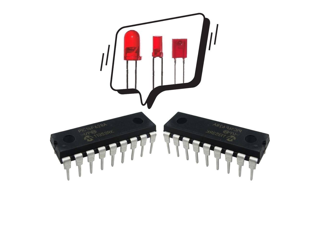
- PIC16F628A: 1 unit.
- LED, any size or color: 1 unit.
- Resistors:
- 330Ω, 1/2 or 1/4W: 1 unit.


Tools and Machinery
- Breadboard: 1 unit.
- PICkit (3 or 4): 1 unit.
- AC/DC Power Adapter to 5V DC, with at least 500mA: 1 unit.
- Jumper or UTP Wires: various.

Breadboard. Respectfully borrowed from Wikipedia. https://commons.wikimedia.org/wiki/File:400_points_breadboard.jpg 
PICkit 4 
AC/DC adapter 
UTP cable. Respectfully borrowed from Wikipedia. https://commons.wikimedia.org/wiki/File:UTP_cable.jpg 
Jumper Wires. Respectfully borrowed from Wikipedia. https://en.wikipedia.org/wiki/File:A_few_Jumper_Wires.jpg
Code for Hello World
Open a new project in MPLAB IDE, select the PIC16F628A and create a C file. This process is written with further detail in this post.
Setting the Configuration and Main Function
For programming PIC microcontrollers, I personally divide the configuration function and the main function; but for now I put everything together, just for simplicity.
Libraries and Compiler
In order to work the entire project, make sure to include the Standard Library and the Compiler. Just add these lines in the first lines of the file.
#include <stdlib.h>
#include <xc.h>
Configuration Bits
The first place we need to attend in the microcontroller are the Configurations Bits. This tool helps us to set or reset the operation mode of some peripherals, such as the MCLR (Master Clear), WDT (Watchdog Timer) and a few more. For this PIC in particular, you will have 8 parameters to configure. Advanced microcontrollers dozens of parameters to configure.
Next to the Output window tab (bottom window of the IDE), click on Configuration Bits. For this tutorial, select the internal oscillator (INTOSCIO). Configure the rest of the bits as shown in the text below. Then click on “Generate Source Code to Output“, copy all the lines and paste it in the code.
config(){
  #pragma config FOSC = INTOSCIO
  #pragma config WDTE = OFF
  #pragma config PWRTE = ON
  #pragma config MCLRE = OFF
  #pragma config BOREN = ON
  #pragma config LVP = OFF
  #pragma config CPD = OFF
  #pragma config CP = OFF
}
Let's configure the I/O pins.
This project will require one output for a LED. It is recommended that non-used pins in any microcontroller are set to input pins; this will help accidental pin burns if it makes contact with the power source. Now remember this rule for programming:
- 1 stands for input or set or on.
- 0 stands for output or reset or off.
Plus, the 0b is an indication that such number is binary.
TRIS and PORT
The PIC16F628A has 3 groups of pins. Power pins (VDD and VSS), group A (RA0, RA1…, RA7) and group B (RB0, RB1…, RB7). The following picture helps you locate each pin.

Each controlled by registers that carries its letter. For controlling the ports, you need to learn the existence of two important registers:
- TRISC: it decides if the pin will work as input or output.
- PORT: if set as output, it decides if the pin will be on 1 or off 0.
Set all pins in the group A to inputs except for the last one. To do this, write this line using the TRISA register. Since this a 8-bit microcontroller, TRISA has 8 bits of configuration. The value to assign starts with 0b (binary indicator) and then from RB7 to RB0, 8 in total. In other words, the variable TRISA should be used like this:
TRISA = (Binary Indicator) RA7 RA6 RA5 RA4 RA3 RA2 RA1 RA0 ;
Translated into C programing language:
TRISA= 0b11111110;
That last 0 means that the pin RA0 will work as an output while the rest, from RBA to RA7 will work as inputs; they will also be unused.
Identically as PORTA, let's configure TRISB for all to pins to behave as inputs.
TRISB= 0b11111111;
Bonus! Empty the PORT register
I recommend you, to write a ‘0’ to the entire port after you have configure the TRIS register; whenever you have programmed it as Input pin (for reading) or as Output pin (for writing). Just in case it has prewritten values.
PORTA=0;
PORTB=0;
Turning on the LED
Just a VERY simple line of code that will do the job. The following line will access just the pin 0 from the PORTA (or group A, as I call it earlier).
PORTAbits.RB0=1;
And that's all the code for the “Hello World” of microcontrollers.
Download the code of Hello World
If you would like to see and read the whole code through, enter your name and e-mail in the form below to download the project. I promise that I won't send you spam; just relevant content to the blog. If you don't see any form below, please click here.
Schematic of Hello World
For reference, here is the schematic for the Hello World for PIC microcontrollers project.

Picture of Hello World
After programming the PIC microcontroller, the code works as these images show it.
Next Post
Now let's decide when it will turn on and off. In the next posts, I will write about Flow Control and how to use a push-button to give the order to turn on and off .
techZorro's Index of Content
Keep Reading!
- 008 – Variable Frequency Drives: how this controller can transform induction motors forever
 AC induction motors can be transformed into a highly controllable machine with Variable Frequency Drives or VFD. Click here to listen.
 - 006 – Regenerative Braking, an awesome Feature found in Electric MotorsThis episode is related to this hidden feature of electric motors called regenerative braking. Click here to listen.
- 005 – 7 types of Electric Motors that you should know aboutThere are several types of electric motors that differs in efficiency, power, cost, torque output, etc. Click here to listen.
- 004 – AC Voltages, Frequencies and Plugs around the WorldLet's talk about electricity! Specifically about how the standards around the world. Click here to listen.
- 002 – RISC vs CISC, how a few Differences are crucial to ComputingToday in the market is found two kinds of processor architectures: RISC and CISC. Both have some advantages. Click here to listen.
You have reached this far!
Thank you for reading the blog post. Your comments and suggestions are welcomed. At the bottom of this page, leave a message or just say hi! The whole team of techZorro will appreciate it. Don't forget to share it on social media as well.
techZorro’s Index of Content
Click on the following link to browse likewise content in the blog in techZorro. This index will help you see what you are looking for in a bird’s eye view.
techZorro's Newsletter!
If you enjoyed this blog post, please subscribe to techZorro’s newsletter so you don’t miss any future blog posts!
[…] a previous post called Hello World, a LED was simply turned on. This post is about blinking the LED (turn it on and off repeatedly), […]