
About PWM.
Hello everyone, Juditova here!
The Pulse Modulation Width (PWM) helps any microcontroller tremendously on most control tasks. You see, PWM makes the connected device to believe its connected to a variable DC source. If done correctly, it can be also a variable AC source!
The PIC used in this tutorial is the PIC16F628A, which was the second PIC I ever programmed. I will use it on this guide because it's easy to implement, all pins can be used a I/Os (except RA5, Vss and Vdd) and has an internal oscillator.
You can check more details about the microcontroller in this link.
Resources.
What's is needed in order to configure a PWM output? Let's check it out.
First of all, your PIC microcontroller requieres a Capture/Compare/PWM (CCP) Module. This module shares resource across these 3 functions. Enabling 1 of them means disabling the other two, remember this.
Please download the datasheet of this microcontroller.
On page 1. under the “Peripheral Features” section, you can see the description of the CCP module. It allows us to control the intensity of the PWM in steps of 10-bits.

In chapter 9 on page 55, the CCP module section is explained. For PWM configuration, it's required to configure the CCP1CON register for our purposes.

The CCP1X and CCP1Y bits are used in addition a 8-bit register to make the PWM a 10-bit control. These are the least significant of them.
The next configuration required is to determine the mode of operation of CCP. As explained before, CCP can work as Capture, Compare and PWM mode. So, we have to specify that it will work as PWM by setting the following bits.
CCP1M3 = 1;
CCP1M2 = 1;
Notice that the other bits (CCP1M1 and CCP1M0) doesn't need to be set.
What resource does PWM takes completely over? While Capture and Compare uses Timer1, PWM will use Timer2 and leave the Timer1 unused. This means, the microcontroller cannot use Timer2 for other purposes.
| CCP Mode | Timer Resource |
| Capture | Timer1 |
| Compare | Timer1 |
| PWM | Timer2 |
Now let's jump into section 9.3 of the datasheet which is the complete explanation of the use of PWM. First of all, take note that the output pin of the PWM, in this case the RB3, must cleared.
PORTBbits.RB3=0;
Downloads
This attached file with help you (as it had helped me) for the calculation of the PWM operation. I will make references to this file for the rest of this post.
Frequency
What's next? Of course, the PWM frequency setup! So which frequency should we set? Obviously, it would depend on 2 things:
- If a transistor is connected to the PWM output, then we will need to know the maximum switching frequency recommended by the manufacturer. Too much frequency and the power losses associated with switching will skyrocket!
- The device that will be attached to PWM end. If you are using a motor, any frequency above 15KHz is recommended, for most cases. If you want to control the backlight of an LCD or control some LEDs, then 500Hz should be fine.
The advantage of using the CCP module is the convenience of PWM through hardware! You see, programming and attending the interrupts of the tasks involved with it, specially at high frequencies, requires a lot of software recourses and debug. This works like a “set it and forget it” feature.
Once you know the frequency that your PWM will have to work at, calculate the associated parameters with the help of the file “PWM-Calculator_RO”. The zones marked with green requieres the user input.
Resolution
On the file “PWM-Calculator_RO” you can find the calculator for the maximum resolution of the PWM. If you set too high the frequency, you will lose the PWM maximum resolution unless you increment the frequency of your oscillator. A 10-bit resolution means you can assign values from 0 to 1023, while in 8-bit resolution, you can assign only from 0 to 255. You lose control on the end device.
For example, if you want to set the frequency of the PWM to 20KHz, with a 20MHz oscillator you will have 10-bit resolution (19.53KHz actually). With a 4MHz however, you will have only 7-bit resolution.
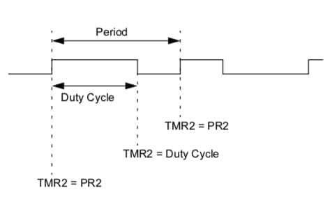
Duty Cycle
After the configuration of the frequency, the PWM is the only thing that's need to be set. This can be done anytime in the code. If you have a 10-bit resolution, you can set any value between 0 and 1023. Here are some examples:
- 1023 equals to 99.9%.
- 511 equals to 49.9%.
- 402 equals to 39.3%.
And how do we assign those values to the PWM? That's a good question! We have to split the 10-bit number in 2 groups: a 8-bit number and a 2-bit number in different registers. Because assigning a 10-bit to 2 different registers requires that you understand bitwise operations, follow this link to learn more about this.
The PWM Duty Cycle is divided in 2 registers:
- CCPR1L (Most significant): From bit 0 to 7.
- CCP1CON (Least significant): From bit 4 to 5.
For example, the number 402 (in decimals) which is 110010010 (in binary), has to be assigned this way:
CCPR1L= 1100100
CCP1CON=xx10xxxx
The ‘x' means “don't care”. And we have to leave them untouched. Only the bits 4 and 5 has to be changed. One way is to shift this 2 bits until they fir in their place. But fortunately for us, this 2 bits has a name and address that can be easily located: CCP1X and CCP1Y (one bit each). The PWM Duty Cycle value has to be stored in a 16 bit variable (I know, we are only going to use 10 bits) and we are going to call it ‘value'.
To assign to the CCPR1L register, we have to shift ‘value' two positions to the right. This will leave out the two least significant bits out (bye bye) and transforms the 10-bit number into a 8-bit number:

To assign to CCP1X, transform the entire number into zeros, except the number in the second position:

To assign to CCP1Y:

Function
This code does what I just explained. It is written in C on MPLAB IDE.
void PWM(uint16_t value) {
	CCPR1L = value >> 2;
    CCP1CONbits.CCP1X = (value & 0x02) >> 1;
    CCP1CONbits.CCP1Y = (value & 0x01);
 }
Setup
After you have read through this tutorial, it's time to add the parameters to the registers associated with PWM. On this example
void Config() {
  //PWM.
     PR2 = 63; //PR2 value on it's Register.
     CCPR1L = 0; //Most significative bits.
     CCP1X = 0; CCP1Y = 0; //Least significative bits.
     T2CKPS1 = 0; T2CKPS0 = 0; //Prescaler.
     TMR2ON = 1; //Turns Timer 2 on.
     CCP1M3 = 1; CCP1M2 = 1; //Configuration PWM.
}
Conclusion
This tutorial explained how to configure the PWM feature in the PIC16F28A. It show the code written in C, along the datasheet link and a spreadsheet tool used for calculation.
On the next tutorial, I will explain how to program the actual microcontroller and you will see it in action.
Table of Contents
You have reached this far!
Thank you for reading the blog post. Your comments and suggestions are welcomed. At the bottom of this page, leave a message or just say hi! The whole team of techZorro will appreciate it. Don't forget to share it on social media as well.
techZorro’s Index of Content
Click on the following link to browse likewise content in the blog in techZorro. This index will help you see what you are looking for in a bird’s eye view.
techZorro's Newsletter!
If you enjoyed this blog post, please subscribe to techZorro’s newsletter so you don’t miss any future blog posts!
techZorro's Index of Content
Keep Reading!
- 008 – Variable Frequency Drives: how this controller can transform induction motors forever
 AC induction motors can be transformed into a highly controllable machine with Variable Frequency Drives or VFD. Click here to listen.
 - 006 – Regenerative Braking, an awesome Feature found in Electric MotorsThis episode is related to this hidden feature of electric motors called regenerative braking. Click here to listen.
- 005 – 7 types of Electric Motors that you should know aboutThere are several types of electric motors that differs in efficiency, power, cost, torque output, etc. Click here to listen.
- 004 – AC Voltages, Frequencies and Plugs around the WorldLet's talk about electricity! Specifically about how the standards around the world. Click here to listen.
- 002 – RISC vs CISC, how a few Differences are crucial to ComputingToday in the market is found two kinds of processor architectures: RISC and CISC. Both have some advantages. Click here to listen.