
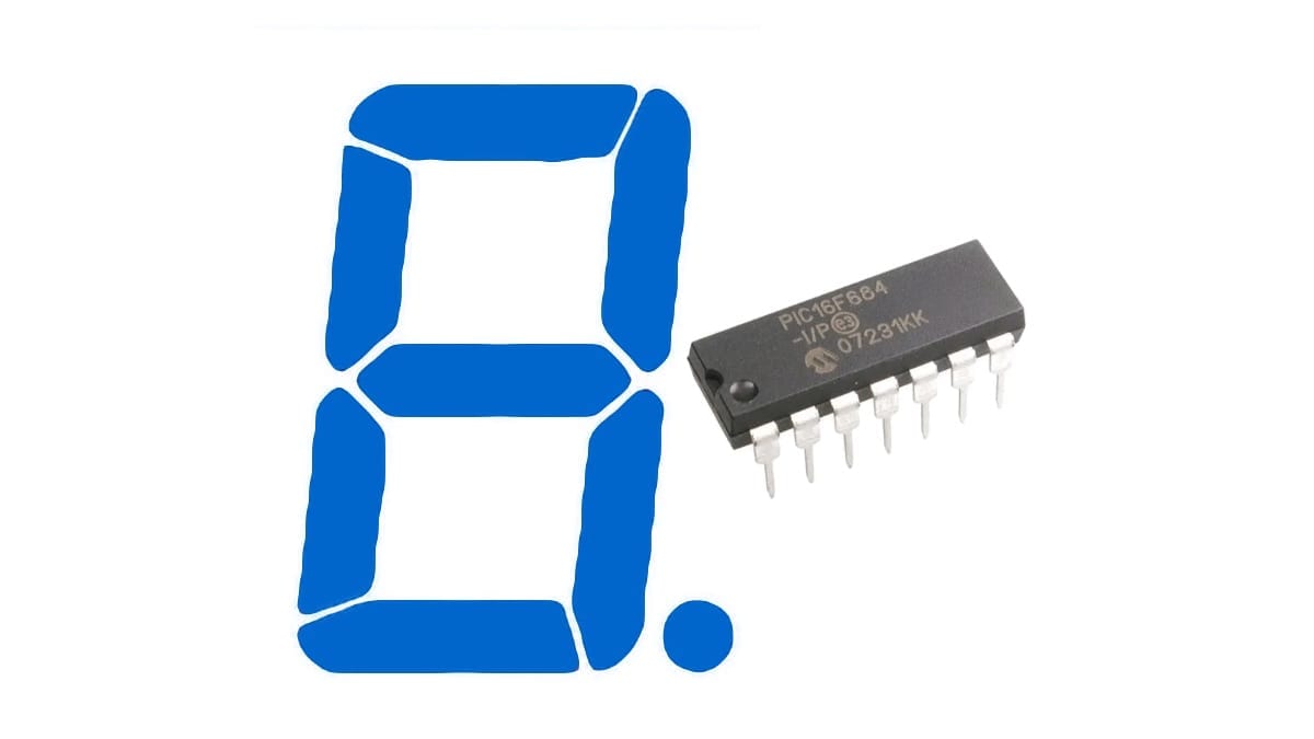
7-segment displays are practical and intuitive to read numbers and symbols out of PIC microcontroller, which are intuitively recognizable for humans. Because the displays are made out of LEDs, it's easy to control and show the right number. This tutorial is about a sequence where all the numbers are displayed, one second at a time. Timer 1 is used for counting the seconds. At the end, you can download the code for free. Continue reading to learn how to drive 7-segment displays.
Before reading this, you will need to know how to setup MPLAB IDE and how to connect the PICkit to the PIC microcontroller. If not, check them out first. Check out also another projects for beginners in 8-bit PIC microcontrollers.
Table of Contents
Requirements to drive 7-Segment Displays
Components and Devices
In this tutorial, all the components are Through Hole.
- PIC16F684: 1 unit.
- Resistors:
- 330Ω, 1/2 or 1/4W: 7 units.
- Numeral 7-segment displays: 1 unit. In this tutorial, Common Anode are used.
- 32768KHz crystal oscillator: 1 unit.
- Capacitors:
- 22pF: 2 units.


PIC microcontroller
For this tutorial, I will use the 8-bit microcontroller PIC16F684. This one is the very first one that I learned to program. Very practical too. Be sure to select Through Hole or ‘TH' version. Surface Mounted won't fit in the breadboard.

Download the datasheet here. I recommend that you print in reduced A4 all the datasheet because it will serve you as quick reference.
Tools and Machinery
- Breadboard: 1 unit.
- PICkit (3 or 4): 1 unit.
- AC/DC Power Adapter to 5V DC, with at least 500mA: 1 unit.
- Jumper or UTP Wires: various.


7-segment displays. How do they work.
As it was pointed out before, 7-segment displays are made out of LEDs, 7 of them for the number and 1 decimal point. To light up a segment, you have to connect a resistor in series with the LED, as usual with any LED. That's it; that is how you drive a 7-segment display.

The connection
There are two types, Common Anode and Common Cathode. In the first case, the positive power source terminal + is connected directly to a common node and every LED is connected in series to the negative power source terminal –. In the second case, it is exactly the opposite.
For the Common Anode display, there are two pins for the power source and one pin for every segment.

Schematics for 7-Segment Displays
The PIC16F684 has to provide the sink for the current from the 7-segment display, which means that a pin with 0V will turn on a LED. Every segment has to go in series with a 330Ω resistor. It doesn't matter to which pin because that is handled in the code. The 32768Hz crystal must be placed in the RA4 and RA5 pins along with the 22pF capacitors as shown below.


Don't forget to connect the PICkit for programming. After everything is connected, let's see how to drive 7-segment displays with a 8-bit PIC microcontroller.
Code for 7-Segment Displays
Initial Configuration
The PIC16F684 uses the internal 4MHz oscillator, therefore the pins RA4 and RA5 are left to be used as general I/O. Also, MCLR and WDT are turned off.
// PIC16F684 Configuration Bit Settings

// 'C' source line config statements

// CONFIG
#pragma config FOSC = INTOSCIO  // Oscillator Selection bits (INTOSCIO oscillator: I/O function on RA4/OSC2/CLKOUT pin, I/O function on RA5/OSC1/CLKIN)
#pragma config WDTE = OFF       // Watchdog Timer Enable bit (WDT disabled)
#pragma config PWRTE = ON       // Power-up Timer Enable bit (PWRT enabled)
#pragma config MCLRE = OFF      // MCLR Pin Function Select bit (MCLR pin function is digital input, MCLR internally tied to VDD)
#pragma config CP = OFF         // Code Protection bit (Program memory code protection is disabled)
#pragma config CPD = OFF        // Data Code Protection bit (Data memory code protection is disabled)
#pragma config BOREN = ON       // Brown Out Detect (BOR enabled)
#pragma config IESO = ON        // Internal External Switchover bit (Internal External Switchover mode is enabled)
#pragma config FCMEN = ON       // Fail-Safe Clock Monitor Enabled bit (Fail-Safe Clock Monitor is enabled)
The pins used for the 7-segment display are set as outputs. The rest of the registers are turned off, so they don't interfere with the operation.
//Pin Configuration
    TRISA = 0b111011; //RA5 to RA0.
    TRISC = 0b000000; //RC5 to RC0.
    PORTA = 0; //Clean PORTA
    PORTC = 0; //Clean PORTC
    ANSEL=0; //Transforms ALL analog pins into digital I/O pins
    CM2=1; CM1=1; CM0=1; //Turns off the Comparators
    CCP1M3=0; CCP1M2=0; CCP1M1=0; CCP1M0=0; //Capture/Compare/PWM is turned off
    ADON=0; //Turn off the Analog to Digital module
The setup for Timer 1 for 1 second interruptions. If you haven't checked the tutorial yet, please click here.
//Timer 1 configuration
    TMR1CS = 1; //Select the external 32KHz oscillator
    T1OSCEN=1; //Enable the oscillator
    nT1SYNC=1; //There is no need to sync the external clock input for this circuit
    T1CKPS1=0; T1CKPS0=0; //Prescaler of Timer 1
    TMR1H=0x80; //TMR1 initial value for 1 second count
    TMR1L=0x00; //Needed?
    TMR1IF = 0; //Reset the interrupt flag
    TMR1IE = 1; //Set the enable flag
    TMR1ON = 1; //Turn on the counting in the Timer 1
Also, Interrupts must be enabled.
//Enable the interrupts
    PEIE=1; //Enable the peripheral interrupts
    GIE=1; //Enable all the interrupts
Aliases of the pins
The aliases are defined for easy management to avoid clutter and disorder.
//Alias for the 7-segment display
#define f PORTAbits.RA2
#define g PORTCbits.RC0
#define a PORTCbits.RC1
#define b PORTCbits.RC2
#define e PORTCbits.RC3
#define d PORTCbits.RC4
#define c PORTCbits.RC5
Routine of Timer 1
The routine to attend the interruption of Timer 1. Upon each interruption, the sequence advances like turns. Each iteration, it displays a different number in order.
a=1; b=1; c=1; d=1; e=1; f=1; g=1;

switch(sequence){ //Selection by the number
        case(1): //if variable 'Sequence' has the value '1'
            b=0; c=0; break; //then turn on these segments (by turning off the port)
        case(2): //if variable 'Sequence' has the value '2'
            a=0; b=0; g=0; e=0; d=0; break; //then turn on these segments (by turning off the port
        case(3): //if variable 'Sequence' has the value '3'
            a=0; b=0; g=0; c=0; d=0; break; //then turn on these segments (by turning off the port
        case(4): //if variable 'Sequence' has the value '4'
            f=0; b=0; g=0; c=0; break; //then turn on these segments (by turning off the port
        case(5): //if variable 'Sequence' has the value '5'
            a=0; f=0; g=0; c=0; d=0; break; //then turn on these segments (by turning off the port
        case(6): //if variable 'Sequence' has the value '6'
            f=0; e=0; d=0; c=0; g=0; break; //then turn on these segments (by turning off the port
        case(7): //if variable 'Sequence' has the value '7'
            a=0; b=0; c=0; break; //then turn on these segments (by turning off the port
        case(8): //if variable 'Sequence' has the value '8'
            a=0; b=0; c=0; d=0; e=0; f=0; g=0; break; //then turn on these segments (by turning off the port
        case(9): //if variable 'Sequence' has the value '9'
            a=0; b=0; c=0; d=0; f=0; g=0; break; //then turn on these segments (by turning off the port
        default: //if variable 'Sequence' has the value '0'
            a=0; b=0; c=0; d=0; e=0; f=0; //then turn on these segments (by turning off the port
            ;
}
At the end, Timer 1‘s register has to be modified in order to interrupt again every second. If you haven't checked the tutorial yet, please click here.
sequence++; //on the next interrupt, the next number will light up
if (sequence>=10) sequence=0; //if all numbers have shown up, the sequence starts over
//while(1);
//Reassign the values of TMR1
TMR1H=0x80; //TMR1 initial value for 1 second count
TMR1L=0x00; //Needed?
Extra Coding
Don’t forget to add the While(1) in the Main function to make it run forever!
while(1) {

}
Download the code of the 7-Segment Displays
If you would like to see and read the whole code through, enter your name and e-mail in the form below to download the project. I promise that I won't send you spam; just relevant content to the blog. If you don't see any form below, please click here.
Testing the 7-Segment Displays
If you don't know how to compile and code a project into a PIC microcontroller, follow this link for the tutorial.
Let's program the PIC microcontroller and let's see how to drive 7-segment displays. If everything executed properly, you should see a message in the bottom of the Output window confirming that the programming process has been complete.
Photo
A picture of the circuit was taken as reference.

Video
See it with your own eyes.
Conclusion
The tutorial has shown how to drive 7-segment displays with a PIC microcontroller and it works marvelously. The Timer 1 executes every second a change of number in the display. The code and schematic are shown and they are downloadable. Unfortunately, it requires 7 pins for the operation but there is a solution or workaround for this.
The next tutorial will implement an integrated circuit to drive the 7-segment display for us. The main advantage is the reduction of pins required of use.
Resources
- Kingbright SA56-21YWA datasheet on Mouser.com. Link.
You have reached this far!
Thank you for reading the blog post. Your comments and suggestions are welcomed. At the bottom of this page, leave a message or just say hi! The whole team of techZorro will appreciate it. Don't forget to share it on social media as well.
techZorro’s Index of Content
Click on the following link to browse likewise content in the blog in techZorro. This index will help you see what you are looking for in a bird’s eye view.
techZorro's Newsletter!
If you enjoyed this blog post, please subscribe to techZorro’s newsletter so you don’t miss any future blog posts!
techZorro's Index of Content
Keep Reading!
- 008 – Variable Frequency Drives: how this controller can transform induction motors forever
 AC induction motors can be transformed into a highly controllable machine with Variable Frequency Drives or VFD. Click here to listen.
 - 006 – Regenerative Braking, an awesome Feature found in Electric MotorsThis episode is related to this hidden feature of electric motors called regenerative braking. Click here to listen.
- 005 – 7 types of Electric Motors that you should know aboutThere are several types of electric motors that differs in efficiency, power, cost, torque output, etc. Click here to listen.
- 004 – AC Voltages, Frequencies and Plugs around the WorldLet's talk about electricity! Specifically about how the standards around the world. Click here to listen.
- 002 – RISC vs CISC, how a few Differences are crucial to ComputingToday in the market is found two kinds of processor architectures: RISC and CISC. Both have some advantages. Click here to listen.
[…] this post, a microcontroller PIC16F684 drives a 7 segment LED display. Every second, the number in the […]
[…] Instead of using the pins of a microcontroller as they are named exactly, call them instead with the help of a Macro. If the main advantage is the simplicity, the secondary advantage is easiness to be reassigned in case the pin needs to change; the rest of the code is left unchanged! The following example is extracted from a tutorial about How to drive 7-Segment Displays with a 8-bit PIC. […]
[…] see the entire code of the example mentioned above, click here to learn […]