
A push button is a simple method to give to the microcontroller an input capability. Any user can push a button or press a switch to activate a specific function or feature.
In this post, you will learn how to read a push button to turn on an LED. This concept of input and output, or simply ‘I/O', is essential for future projects since many electronic devices works entirely depending on one or multiple inputs.
Before reading this, you will need to know how to setup MPLAB IDE and how to connect the PICkit to the microcontroller. If not, check them out first. Check out also another projects for beginners in 8-bit PIC microcontrollers.
Table of Contents
Requirements for Push Buttons
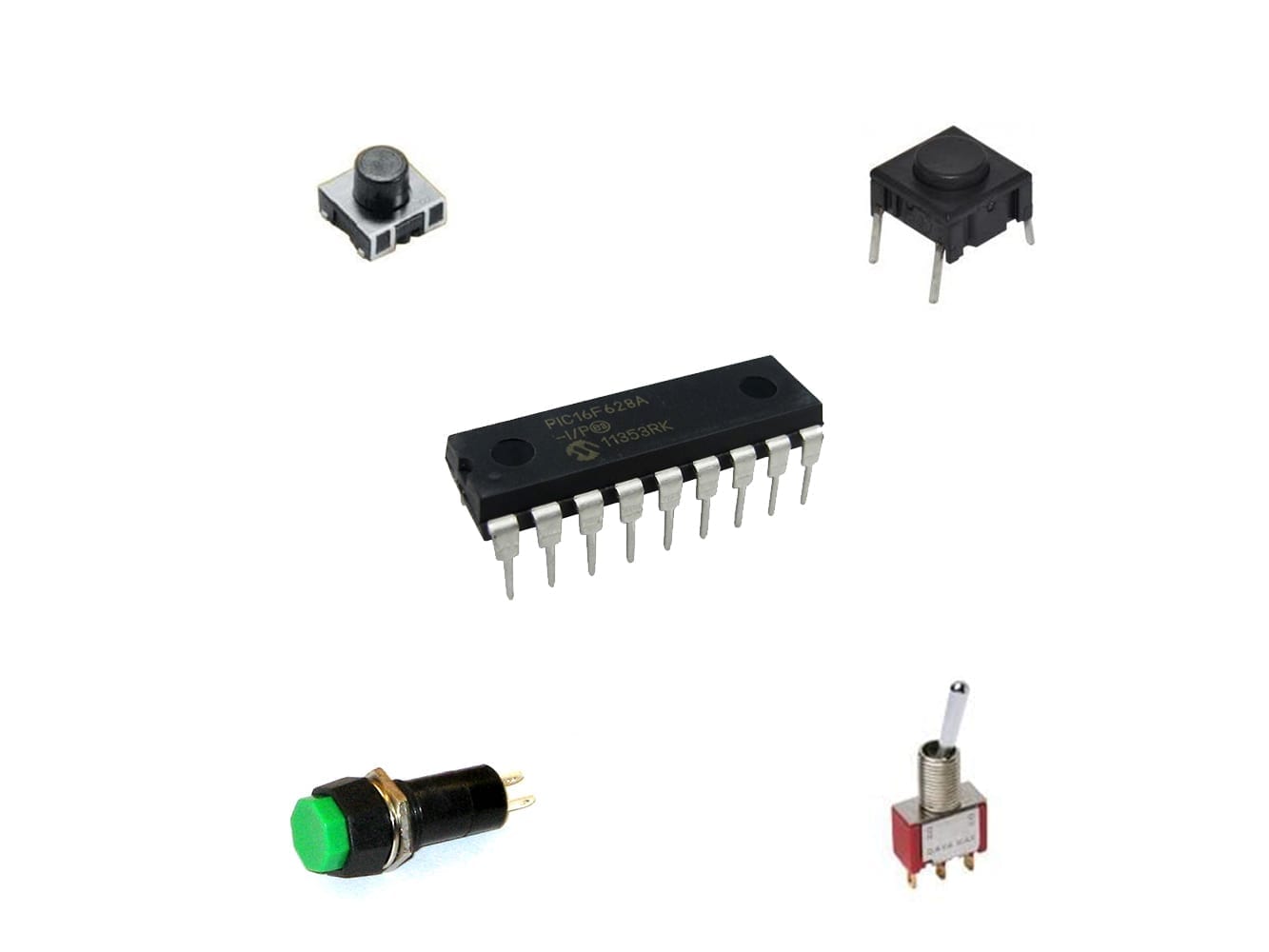
Components and Devices
In this tutorial, all the components are Through Hole.
- PIC16F628A: 1 unit.
- LED, any size or color: 1 unit.
- Resistors:
- 330Ω, 1/2 or 1/4W: 1 unit.
- Any resistor between 1KΩ and 10KΩ, 1/2 or 1/4W: 2 units.
- Push button, type SPST: 2 units.


Tools and Machinery
- Breadboard: 1 unit.
- PICkit (3 or 4): 1 unit.
- AC/DC Power Adapter to 5V DC, with at least 500mA: 1 unit.
- Jumper or UTP Wires: various.


Schematic of Push Buttons
Voltage Divider
In order to use a push button, you need to give the proper signal to the microcontroller. It will understand a logic 1 and logic 0 (which is 5V and 0V for this tutorial, respectively) and such thing can be done with a voltage divider. If you are not familiarized with this topic, click on this button to go to the tutorial:
Schematic
The push button could be connected to any general purpose I/O pin of the microcontroller; which means, if it isn't used in another task. The Port B is optimized for inputs, because it has dedicated pull-up resistors. I will cover that topic in another post.
For now, let's put our own pull-up resistor (any value between 1KΩ and 10KΩ) and the push button on the pin RB5 in the breadboard as shown in the schematic.
Place the LED on pin RB3 with the resistor in the breadboard. LEDs do have polarity! Make sure that the long wire is connected to the output pin RB3. The corresponding 330Ω resistor has to be placed after the short wire from the LED and the other pin to ground (0V – negative).

Photos
A few pictures of the assembled circuit on the breadboard.


Code of Push Buttons
Configuration() function
Just like the previous tutorial, we have to set the Configuration Bits. The exact code can be found below.
- Turn on the internal oscillator (4MHz).
- Turn off the Watchdog Timer
- Turn on the Master Clear, Power-Up Timer and Brown-out Timer.
- The rest is unimportant for now.
config(){ // CONFIG
    #pragma config FOSC = INTOSCIO  // Oscillator Selection bits (INTOSC oscillator: I/O function on RA6/OSC2/CLKOUT pin, I/O function on RA7/OSC1/CLKIN)
    #pragma config WDTE = OFF       // Watchdog Timer Enable bit (WDT disabled)
    #pragma config PWRTE = ON       // Power-up Timer Enable bit (PWRT enabled)
    #pragma config MCLRE = ON       // RA5/MCLR/VPP Pin Function Select bit (RA5/MCLR/VPP pin function is MCLR)
    #pragma config BOREN = ON       // Brown-out Detect Enable bit (BOD enabled)
    #pragma config LVP = OFF        // Low-Voltage Programming Enable bit (RB4/PGM pin has digital I/O function, HV on MCLR must be used for programming)
    #pragma config CPD = OFF        // Data EE Memory Code Protection bit (Data memory code protection off)
    #pragma config CP = OFF         // Flash Program Memory Code Protection bit (Code protection off)
    //More code comes after this line
}
Pinout Configuration
All PORTA is unused, therefore let's leave it as input (because it has higher impedance). Just the RB3 from PORTB is going to be used as output, therefore
TRISA=0b11111111; //They are unused, therefor leave them with '1'.
TRISB=0b11110111; //Only RB3 will be an output (therefore the '0'). Leave the rest of 1.
PORTA=0; //Clean the ports.
PORTB=0;
How to use ‘while' and ‘if'
By the way, if you aren't familiar with Control Flow (if, while, for, etc) please follow this link to learn more, since you are going to use it in this tutorial.
Implementing Control Flow
The code needs to verify many times per second if a button has been pressed. The rest of the code must be written inside the ‘while loop'. Make sure to place a 1 as condition; this way it will always execute the code inside of it.
while(1) {

}
How to read the push button
The code must ask to the microcontroller if a button has been pressed. How does the microcontroller knows that? Checking the logic value (either 0 or 1) of the pin and there is a register to know that.
- If YES, it was pressed, then
- Do certain action.
- or don't do anything (useful in certain cases).
- If NO, it was not pressed, then
- Do certain action.
- or don't do anything (useful in certain cases).
PORTBbits is a register that contain all the 8 values from PORTB (from RB0 to RB7). In order to know the value of the pin RB5, you have to call the value of the register,
if (!PORTBbits.RB5)
Let's turn it on
Just as checking the status of the RB5, you have to assign a value to the RB3, where the LED is placed.
if (!PORTBbits.RB5) PORTBbits.RB3=1;
Let's turn it off
When the button is not pressed, let's just turn it off, shall we? Let's give a 0 value when the condition is not true. You will use the else instruction.
if (!PORTBbits.RB5) PORTBbits.RB3=1;
else PORTBbits.RB3=0;
Download the code of Push Button
If you would like to see and read the whole code through, enter your name and e-mail in the form below to download the project. I promise that I won't send you spam; just relevant content to the blog. If you don't see any form below, please click here.
Testing the Push Button
If you don't know how to compile and code a project into a PIC microcontroller, follow this link to my tutorial.
If everything executed properly, you should see a message in the bottom of the Output window confirming that the programming process has been complete.


As you can see above, the LED is turned on as the button is pressed and turned off when released. Mission accomplished!
Next Chapter
The following tutorial will guide you through transistor switching, oriented to PIC microcontrollers.
Do you have a question? Any suggestions? Let me know in the comments below.
techZorro's Index of Content
Keep Reading!
- Macros on C, how to create useful Aliases for the Code
 Macros are tremendously helpful in saving time and clutter in code writing. This tutorial includes tutorials on C. Click here to read.
 - Switch in C, the neat multiple decision maker in Control Flow
 In Control Flow, Switch replaces multiples if's and merges into one elegant decision making solution. Click here to read.
 - While loop in C language, the ‘ask first' of Control Flow
 While in C is great for creating loops using Control Flow. It's great for repeated tasks and counters! Click here to read more.
 - Code Template, an easy guide for PIC Microcontrollers in C
 Writing a program with order is a time saver. Download today the code template for PIC microcontrollers for free. Click here to read more.
 - Functions in C Programming Language
 Functions lets you reutilize code efficiently and opens up libraries done by others. Click here to learn to use functions in C.
You have reached this far!
Thank you for reading the blog post. Your comments and suggestions are welcomed. At the bottom of this page, leave a message or just say hi! The whole team of techZorro will appreciate it. Don't forget to share it on social media as well.
techZorro’s Index of Content
Click on the following link to browse likewise content in the blog in techZorro. This index will help you see what you are looking for in a bird’s eye view.
techZorro's Newsletter!
If you enjoyed this blog post, please subscribe to techZorro’s newsletter so you don’t miss any future blog posts!